
see also: evolution propeller design methods
Duct fan for a heat exchanger, designed via AI First propeller in Heliciel: the method step by step One optimal point: design and off-designAxial pump and propeller pump: how it works, waterjet and sizing
An axial pump, also called a propeller pump or helical pump, is a pump that moves a large flow while creating only a small pressure change. Its propeller turns inside a duct and pushes the fluid along the axis, without throwing it outward. It is found mainly in irrigation and, in another form, as the waterjet (pump-jet) on jet skis, shallow-draft outboards and some submarines.
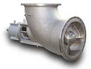
An axial propeller pump: the fluid enters and leaves along the propeller axis.
Contents:
- Axial pump and propeller pump: the principle
- Axial pump propeller calculation: flow rate and pressure change
- Waterjet and pump-jet: strong thrust from a small propeller
- Blade root, leakage and guide vanes
- Flow versus pressure trade-off, and cavitation
1: Axial pump and propeller pump: the principle
The propeller of an axial pump looks like a ducted boat propeller. The difference lies in what we are after. For a boat, we want thrust. For a pump, we want a pressure change at a given flow rate.
The flow rate you want therefore sets the operating point of the pump propeller. You impose that flow rate; Heliciel then computes the thrust and the pressure change the propeller produces at that flow.
2: Axial pump propeller calculation: flow rate and pressure change
The propeller is built so that, at the required flow rate, it creates a pressure difference equal to the pressure loss of the duct the fluid flows through. In an installation, the operating point sits at the intersection of two curves: the network pressure loss against flow rate, and the pump pressure change against the same flow rate.
The sizing method is that of a propulsion propeller with a duct. Since the pressure change is the main objective, the propeller is heavily loaded. Heliciel displays this pressure delta for an axial pump, next to the axial force, the torque and the efficiencies:
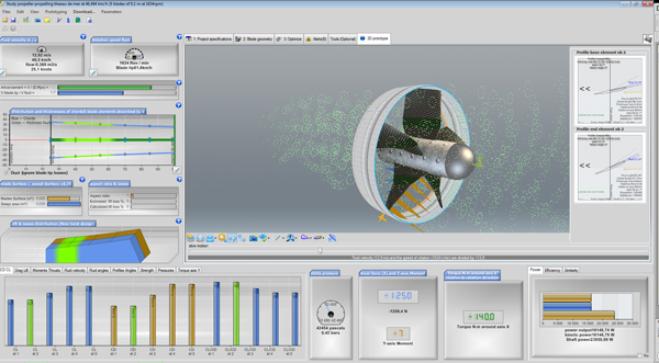
Heliciel results for a ducted axial pump: on this capture, the pressure delta dial reads 42,454 pascals (0.42 bar), next to the axial force dial, the torque dial and the power and efficiency bars.
To use the pump in a network, Heliciel exports the propeller (duct option ticked) in the Mecaflux Pro3D pump format, which derives the operating point of the network connected to it: modelling a propeller pump and exporting it to a network.
3: Waterjet and pump-jet: strong thrust from a small propeller
Pump-jets used as propulsion for submarines and jet skis, or fitted to outboard engines, belong to this category. The propeller diameter is sometimes limited by the draft, and by the operating speed that caps the blade tip speed (cavitation).
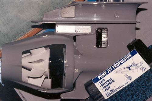
An outboard pump-jet: the propeller turns in a tight duct, which limits blade tip leakage.
When you want strong thrust from a small propeller, you meet again the problem of pressure leakage at the blade tip, and also at the blade roots. The duct answers the first; the blade root radius answers the second.
The efficiency of ducted boat propellers is good only at low speed. But for a recreational jet ski, a submarine that must accelerate very hard when needed, a shallow-draft outboard or a waterjet built into the hull, efficiency is no longer the point. The point is to create strong thrust with a small propeller.
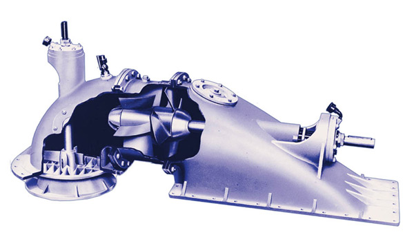
Cutaway of a waterjet: the axial pump propeller turns in the pump body, and the jet leaves through the nozzle.
4: Blade root, leakage and guide vanes
These constraints lead to ducted propellers with a blade root around 0.5 times the radius. According to the orders of magnitude we use, the pressure created by a propeller peaks around 0.75 times the blade tip radius. The root cannot create a large pressure change, because its apparent speed is low. Placing the root at 50% of the tip radius therefore raises the pressure and limits leakage.
The strong blade lift also implies a large tangential induced velocity, that is, the fluid is set into rotation. This rotation produces no thrust and is an energy loss. It can be recovered with fixed guide vanes, placed behind the propeller to straighten the flow, or in front of it to pre-orient the fluid entering.
5: Flow versus pressure trade-off, and cavitation
A compromise must be found between flow rate and achievable pressure, according to the cavitation limit on the blades. The more heavily loaded the propeller, the stronger the suction on the blade upper surface, and the closer cavitation gets.
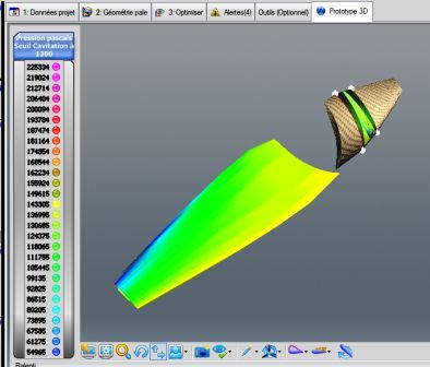
The "3D Prototype" tab of Heliciel: the blade is coloured by the pressure at its surface, with a scale in pascals and a cavitation threshold to read on the legend.
Here is an axial pump propeller study in Heliciel: the blade, the duct and the wake are modelled in 3D, and the performance is computed each time the operating point changes.
To go further, we can see how to size an axial fan for an air-handling network, which follows the same logic of flow and pressure change with air, or compare with the general case of the propulsion propeller.
 Global site map
 Mecaflux
 Tutorials Mecaflux Pro3D
 Tutorials Heliciel
 Tutorials Heliciel PRO CFD
 Mecaflux Store
 Compare software functions
 Quotes, Orders, Payment Methods
 project technical studies